Load balancing VPLS traffic

Featured

In this post, we will demonstrate load balancing VPLS traffic using multiple LSP tunnels.

Topology

VPLS-VLAN-to-VLAN

Configuration


[edit]
lab@PE1# 

interfaces {

    ge-1/0/7 {
        description "LINK - PE2 ge-1/0/7";
        unit 0 {
            family inet {
                address 10.10.101.1/24;
            }
            family mpls;
        }
    }

    ge-1/1/7 {
        description "LINK - PE2 ge-1/1/7";
        unit 0 {
            family inet {
                address 10.10.102.1/24;
            }
            family mpls;
        }
    }

    ge-1/0/6 {
        vlan-tagging;
        encapsulation flexible-ethernet-services;
        /* VLPS Vlan */
        unit 600 {
            description "vpls interface to SW1";
            encapsulation vlan-vpls;
            vlan-id 600;                
            family vpls;
        }
    }
}

protocols {
    rsvp {
        load-balance bandwidth;
        interface all;
    }
    mpls {
        label-switched-path PE1-to-PE2-LSP1 {
            to 10.1.1.22;               
            bandwidth 200m;
            no-cspf;
            primary via-Ge1;
        }
        label-switched-path PE1-to-PE2-LSP2 {
            to 10.1.1.22;
            bandwidth 200m;
            no-cspf;
            primary via-Ge2;
        }
        path via-Ge1 {
            10.10.101.2;
        }
        path via-Ge2 {
            10.10.102.2;
        }
        interface ge-1/0/7.0;
        interface ge-1/1/7.0;
    }
    bgp {
        local-as 65000;
        group PEs {
            type internal;
            local-address 10.1.1.11;
            family inet {
                unicast;
            }
            family inet-vpn {
                unicast;
            }
            family l2vpn {
                signaling;
            }
            neighbor 10.1.1.22;
        }
    }
    ospf {
        traffic-engineering;
        area 0.0.0.0 {
            interface ge-1/0/7.0 {
                interface-type p2p;     
            }
            interface ge-1/1/7.0 {
                interface-type p2p;
            }
            interface lo0.0;
        }
    }
}

routing-instances {
    VPLS-1 {
        instance-type vpls;             
        interface ge-1/0/6.600;
        route-distinguisher 10.1.1.11:11;
        vrf-target target:65000:100;
        protocols {
            vpls {
                site-range 10;
                site Site1 {
                    site-identifier 1;
                }
            }
        }
    }
}

policy-options {
    policy-statement per-flow-load-balance {
        then {
            load-balance per-packet;
        }
    }
}

routing-options {
    forwarding-table {
        export per-flow-load-balance;
    }
}

Verification

Behaviour on different Junos version may be different. Note that on MX5, the load-balancing is supported under forwarding-options enhanced-hash-key configuration, rather than hash-key. In fact, we need to remove all the hash-key config, otherwise, the behaviour is not expected. By default load-balancing is already supported on MX5.

The following command is useful to confirm the hash key configuration:

lab@PE1> request pfe execute command "show jnh lb" target tfeb0 
SENT: Ukern command: show jnh lb
GOT:
GOT: Unilist Seed Configured 0x8bce4c39 System Mac address 00:00:00:00:00:00
GOT: Hash Key Configuration: 0x0000000000e00000 0xffffffffffffffff
GOT:            IIF-V4: No
GOT:          SPORT-V4: Yes
GOT:          DPORT-V4: Yes
GOT:               TOS: No
GOT:
GOT:            IIF-V6: No
GOT:          SPORT-V6: Yes
GOT:          DPORT-V6: Yes
GOT:     TRAFFIC_CLASS: No
GOT:
GOT:          IIF-MPLS: No
GOT:      MPLS_PAYLOAD: Yes
GOT:          MPLS_EXP: No
GOT:
GOT:       IIF-BRIDGED: No
GOT:     MAC ADDRESSES: Yes
GOT:     ETHER_PAYLOAD: Yes
GOT:      802.1P OUTER: No
GOT:
GOT: Services Hash Key Configuration:
GOT:          SADDR-V4: No
GOT:            IIF-V4: No
GOT:
LOCAL: End of file

lab@PE1> show mpls lsp statistics    
Ingress LSP: 3 sessions
To              From            State     Packets            Bytes LSPname
10.1.1.22       10.1.1.11       Up           1284           130968 PE1-to-PE2-LSP1
10.1.1.22       10.1.1.11       Up           1208           123216 PE1-to-PE2-LSP2
Total 3 displayed, Up 3, Down 0

Egress LSP: 3 sessions
To              From            State     Packets            Bytes LSPname
10.1.1.11       10.1.1.22       Up             NA               NA PE2-to-PE1-LSP1
10.1.1.11       10.1.1.22       Up             NA               NA PE2-to-PE1-LSP2
Total 3 displayed, Up 3, Down 0

Transit LSP: 0 sessions
Total 0 displayed, Up 0, Down 0

lab@PE1> monitor label-switched-path PE1-to-PE2-LSP2 

To 10.1.1.22, From 10.1.1.11, state: Up
  LSPname: PE1-to-PE2-LSP2, type: Ingress
  Label in: -, Label out: 3
  Port number: sender 4, receiver 7368, protocol 0
  Record Route:  10.10.102.2

  Traffic statistics:                      pps/bps
    Output packets:            38813             0
    Output bytes:            3958926             0

IPSec tunnel between 2 Cisco IOS routers

In this lab, we are going to configure a simple IPSec tunnel between two Cisco IOS routers, and run OSPF over the tunnel.

Below are parameters for the IPSec tunnel, which is the same as in the IPSec lab between 2 SRX firewalls.

Phase 1:

  • Authentication method: Pre-shared Key
  • dh-group: group2
  • Authentication algorithm: md5
  • encryption algorithm: 3des-cbc
  • lifetime: 86400

Phase 2:

  • ESP protocol
  • Authentication algorithm: hmac-md5-96
  • Encryption algorithm: 3des-cbc
  • Lifetime: 3600

All internal traffic (in this lab is between the two loopback addresses) is allowed via the tunnel.

Topology

IPSec Tunnel IOS routers

Configuration

Below is the config on one router (R1). Config on the other router (R2) is similar.

IKE / ISAKMP Phase 1 config

crypto isakmp policy 1
 encr 3des
 hash md5
 authentication pre-share
 group 2
! 0.0.0.0/0 is to define traffic to be encrypted.
crypto isakmp key cisco address 0.0.0.0 0.0.0.0
crypto isakmp keepalive 10

IPSec Phase 2 Config

crypto ipsec transform-set R1-R2-TSET esp-3des esp-md5-hmac 
!
crypto ipsec profile R1-R2-PROFILE
 set transform-set R1-R2-TSET 
!
interface Tunnel0
 description "IPSec tunnel interface"
 ip address 10.10.1.1 255.255.255.252
 tunnel source 123.1.1.2
 tunnel destination 123.1.2.2
 tunnel mode ipsec ipv4
 tunnel protection ipsec profile R1-R2-PROFILE

Routing config (for demonstration/verification purpose).

interface FastEthernet0/0
 description "Internet facing interface"
 ip address 123.1.1.2 255.255.255.252
!
interface Loopback0
 description "Internal facing interface"
 ip address 10.10.100.1 255.255.255.0
!
! Run OSPF via IPSec tunnel
router ospf 1
 log-adjacency-changes
 network 10.10.1.1 0.0.0.0 area 0
 network 10.10.100.1 0.0.0.0 area 0
!

ip route 0.0.0.0 0.0.0.0 123.1.1.1 name Default-to-Internet

Verification

R1#show interfaces tunnel 0
Tunnel0 is up, line protocol is up 
  Hardware is Tunnel
  Description: "IPSec tunnel interface"
  Internet address is 10.10.1.1/30
  MTU 1514 bytes, BW 9 Kbit, DLY 500000 usec, 
     reliability 255/255, txload 1/255, rxload 1/255
  Encapsulation TUNNEL, loopback not set
  Keepalive not set
  Tunnel source 123.1.1.2, destination 123.1.2.2
  Tunnel protocol/transport IPSEC/IP
  Tunnel TTL 255
  Fast tunneling enabled
  Tunnel transmit bandwidth 8000 (kbps)
  Tunnel receive bandwidth 8000 (kbps)
  Tunnel protection via IPSec (profile "R1-R2-PROFILE")
  Last input never, output never, output hang never
  Last clearing of "show interface" counters never
  Input queue: 0/75/0/0 (size/max/drops/flushes); Total output drops: 0
  Queueing strategy: fifo
  Output queue: 0/0 (size/max)
  5 minute input rate 0 bits/sec, 0 packets/sec
  5 minute output rate 0 bits/sec, 0 packets/sec
     434 packets input, 37004 bytes, 0 no buffer
     Received 0 broadcasts, 0 runts, 0 giants, 0 throttles
     0 input errors, 0 CRC, 0 frame, 0 overrun, 0 ignored, 0 abort
     444 packets output, 37470 bytes, 0 underruns
     0 output errors, 0 collisions, 0 interface resets
     0 output buffer failures, 0 output buffers swapped out

R1#show crypto session detail 
Crypto session current status

Code: C - IKE Configuration mode, D - Dead Peer Detection     
K - Keepalives, N - NAT-traversal, X - IKE Extended Authentication

Interface: Tunnel0
Session status: UP-ACTIVE     
Peer: 123.1.2.2 port 500 fvrf: (none) ivrf: (none)
      Phase1_id: 123.1.2.2
      Desc: (none)
  IKE SA: local 123.1.1.2/500 remote 123.1.2.2/500 Active 
          Capabilities:D connid:3 lifetime:23:44:43
  IPSEC FLOW: permit ip 0.0.0.0/0.0.0.0 0.0.0.0/0.0.0.0 
        Active SAs: 2, origin: crypto map
        Inbound:  #pkts dec'ed 96 drop 0 life (KB/Sec) 4386664/2741
        Outbound: #pkts enc'ed 96 drop 0 life (KB/Sec) 4386664/2741

R1#show crypto isakmp ?
  key      Show ISAKMP preshared keys
  peers    Show ISAKMP peer structures
  policy   Show ISAKMP protection suite policy
  profile  Show ISAKMP profiles
  sa       Show ISAKMP Security Associations

R1#show crypto isakmp sa detail
Codes: C - IKE configuration mode, D - Dead Peer Detection
       K - Keepalives, N - NAT-traversal
       X - IKE Extended Authentication
       psk - Preshared key, rsig - RSA signature
       renc - RSA encryption

C-id  Local           Remote          I-VRF    Status Encr Hash Auth DH Lifetime Cap.
3     123.1.1.2       123.1.2.2                ACTIVE 3des md5  psk  2  23:29:57 D   
       Connection-id:Engine-id =  3:1(software)

R1#show crypto isakmp policy  

Global IKE policy
Protection suite of priority 1
        encryption algorithm:   Three key triple DES
        hash algorithm:         Message Digest 5
        authentication method:  Pre-Shared Key
        Diffie-Hellman group:   #2 (1024 bit)
        lifetime:               86400 seconds, no volume limit
Default protection suite
        encryption algorithm:   DES - Data Encryption Standard (56 bit keys).
        hash algorithm:         Secure Hash Standard
        authentication method:  Rivest-Shamir-Adleman Signature
        Diffie-Hellman group:   #1 (768 bit)
        lifetime:               86400 seconds, no volume limit

R1#sh crypto ipsec ?      
  client                Show Client Status
  policy                Show IPSEC client policies
  profile               Show ipsec profile information
  sa                    IPSEC SA table
  security-association  Show parameters for IPSec security associations
  transform-set         Crypto transform sets

R1#sh crypto ipsec sa

interface: Tunnel0
    Crypto map tag: Tunnel0-head-0, local addr 123.1.1.2

   protected vrf: (none)
   local  ident (addr/mask/prot/port): (0.0.0.0/0.0.0.0/0/0)
   remote ident (addr/mask/prot/port): (0.0.0.0/0.0.0.0/0/0)
   current_peer 123.1.2.2 port 500
     PERMIT, flags={origin_is_acl,}
    #pkts encaps: 114, #pkts encrypt: 114, #pkts digest: 114
    #pkts decaps: 115, #pkts decrypt: 115, #pkts verify: 115
    #pkts compressed: 0, #pkts decompressed: 0
    #pkts not compressed: 0, #pkts compr. failed: 0
    #pkts not decompressed: 0, #pkts decompress failed: 0
    #send errors 0, #recv errors 0

     local crypto endpt.: 123.1.1.2, remote crypto endpt.: 123.1.2.2
     path mtu 1500, ip mtu 1500, ip mtu idb FastEthernet0/0
     current outbound spi: 0x5D85C9FC(1569049084)

     inbound esp sas:
      spi: 0x43B60039(1136001081)
        transform: esp-3des esp-md5-hmac ,
        in use settings ={Tunnel, }
        conn id: 2001, flow_id: SW:1, crypto map: Tunnel0-head-0
        sa timing: remaining key lifetime (k/sec): (4386661/2562)
        IV size: 8 bytes
        replay detection support: Y
        Status: ACTIVE

     inbound ah sas:

     inbound pcp sas:

     outbound esp sas:
      spi: 0x5D85C9FC(1569049084)
        transform: esp-3des esp-md5-hmac ,
        in use settings ={Tunnel, }
        conn id: 2002, flow_id: SW:2, crypto map: Tunnel0-head-0
        sa timing: remaining key lifetime (k/sec): (4386661/2560)
        IV size: 8 bytes
        replay detection support: Y
        Status: ACTIVE

     outbound ah sas:

     outbound pcp sas:

Debugging commands:

debug crypto isakmp
debug crypto ipsec

IPSec Tunnel on SRX

In this lab, we are going to configure a simple IPSec tunnel in the main mode (which requires fixed IP at both ends) between two firewalls SRX1 for OAM network, and SRX2 for CORP network.

Below are parameters for the IPSec tunnel.

Phase 1:

  • Authentication method: Pre-shared Key
  • dh-group: group2
  • Authentication algorithm: md5
  • encryption algorithm: 3des-cbc
  • lifetime: 86400

Phase 2:

  • ESP protocol
  • Authentication algorithm: hmac-md5-96
  • Encryption algorithm: 3des-cbc
  • Lifetime: 3600

Firewall policy is configured to allow 2x CORP subnets (VLAN 200 and 201) to access pre-defined applications on VLAN100 in OAM network. OAM network can access Internet except FTP.

Topology

IPSec Tunnel

Configuration

Base config (interface, routing)

interfaces {                            
    protect: ge-0/0/0 {
        description "MGMT Interface - DO NOT DELETE";
        unit 0 {
            family inet {
                address 10.210.14.135/27;
            }
        }
    }
    ge-0/0/3 {
        description "Link to Internet Router";
        vlan-tagging;
        unit 1 {
            vlan-id 1;
            family inet {
                address 123.1.1.2/30;
            }
        }
    }
    ge-0/0/4 {
        description "Link to OAM Virtual Router";
        vlan-tagging;
        unit 100 {
            vlan-id 100;
            family inet {
                /* Limitation of running Junos on VM. 
                 * Reduce MTU to match the other end
                 */
                mtu 1496;
                address 10.10.100.1/24;
            }
        }
    }                                   
    lo0 {
        unit 1 {
            family inet {
                address 192.168.1.1/32;
            }
        }
    }
    st0 {
        unit 0 {
            description "IPSec Tunnel to SRX2 CORP Firewall";
            family inet {
                address 10.10.1.1/30;
            }
        }
    }
}
routing-options {
    static {
        route 0.0.0.0/0 next-hop 123.1.1.1;
    }
}
protocols {
    ospf {
        traceoptions {
            file ospf;
            flag error;
            flag event;
            flag hello;
        }
        area 0.0.0.0 {
            interface st0.0;
            interface ge-0/0/4.100 {    
                interface-type p2p;
            }
        }
    }
    lldp {
        interface all;
    }
}

IPSec configuration

lab@SRX1# show security 
ike {
    proposal phase1 {
        authentication-method pre-shared-keys;
        dh-group group2;
        authentication-algorithm md5;
        encryption-algorithm 3des-cbc;
        lifetime-seconds 86400;
    }
    policy phase1-policy {
        mode main;
        proposals phase1;
        pre-shared-key ascii-text "$9$zyG8F9t0BEcyKCtLNbwJZF369Cu1RSeMX"; ## SECRET-DATA
    }
    gateway phase1-gateway {
        ike-policy phase1-policy;
        address 123.1.2.2;
        dead-peer-detection {
            interval 20;
            threshold 5;
        }
        external-interface ge-0/0/3.1;
    }
}
ipsec {
    proposal phase2 {
        protocol esp;
        authentication-algorithm hmac-md5-96;
        encryption-algorithm 3des-cbc;
        lifetime-seconds 3600;
    }
    policy phase2-policy {
        perfect-forward-secrecy {
            keys group2;                
        }
        proposals phase2;
    }
    vpn to-remote-SRX {
        bind-interface st0.0;
        ike {
            gateway phase1-gateway;
            ipsec-policy phase2-policy;
        }
        establish-tunnels immediately;
    }
}

Security Policy configuration

[edit]
lab@SRX1# show applications 
application Custom-Defined {
    protocol udp;
    source-port 50000;
    destination-port 50001;
}
application-set OAM-Apps {
    application Custom-Defined;
    application junos-telnet;
    application junos-ping;
}

[edit]
lab@SRX1# show security | find policies 

policies {
    /* Sample policy to deny FTP from OAM to Internet */
    from-zone OAM to-zone Untrust {
        policy deny-ftp {
            match {
                source-address any;
                destination-address any;
                application junos-ftp;
            }
            then {
                reject;
            }
        }
        policy allow-all {
            match {
                source-address [ OAM_VL100 OAM_VL101 ];
                destination-address any;
                application any;
            }
            then {
                permit;                 
            }
        }
    }
    from-zone CORP to-zone OAM {
        policy CORP-to-OAM {
            match {
                source-address [ CORP_VL200 CORP_VL201 ];
                /* This sample policy only allow CORP to access VLAN100 in OAM */
                destination-address OAM_VL100;
                application OAM-Apps;
            }
            then {
                permit;
                log {
                    session-init;
                    session-close;
                }
            }
        }
    }
}
zones {
    protect: functional-zone management {
        interfaces {
            ge-0/0/0.0;
        }
        host-inbound-traffic {
            system-services {
                all;
            }
        }
    }
    security-zone OAM {                 
        address-book {
            address OAM_VL101 10.10.101.0/24;
            address OAM_VL100 10.10.100.0/24;
        }
        interfaces {
            ge-0/0/4.100 {
                host-inbound-traffic {
                    protocols {
                        ospf;
                    }
                }
            }
        }
    }
    security-zone Untrust {
        address-book {
            address SRX2 123.1.2.0/30;
            address internet-host 88.88.88.88/32;
        }
        interfaces {
            ge-0/0/3.1;
        }
    }
    security-zone CORP {
        address-book {
            address CORP_VL200 10.10.200.0/24;
            address CORP_VL201 10.10.201.0/24;
        }
        interfaces {
            st0.0 {
                host-inbound-traffic {
                    system-services {   
                        ike;
                    }
                    protocols {
                        ospf;
                    }
                }
            }
        }
    }
}

Verification

lab@SRX1> show interfaces st0 terse 
Interface               Admin Link Proto    Local                 Remote
st0                     up    up  
st0.0                   up    up   inet     10.10.1.1/30    

lab@SRX1> show security ike security-associations 
Index   State  Initiator cookie  Responder cookie  Mode           Remote Address   
3501187 UP     b1dc0e544d88f7bb  d1a0f576f6215442  Main           123.1.2.2       

lab@SRX1> show security ipsec security-associations 
  Total active tunnels: 1
  ID    Algorithm       SPI      Life:sec/kb  Mon lsys Port  Gateway   
  131073 ESP:3des/md5  a88a5f9e 3184/ unlim   -   root 500   123.1.2.2       

lab@SRX1> show security ipsec security-associations index 131073 
  ID: 131073 Virtual-system: root, VPN Name: to-remote-SRX
  Local Gateway: 123.1.1.2, Remote Gateway: 123.1.2.2
  Local Identity: ipv4_subnet(any:0,[0..7]=0.0.0.0/0)
  Remote Identity: ipv4_subnet(any:0,[0..7]=0.0.0.0/0)
  Version: IKEv1
    DF-bit: clear
    Bind-interface: st0.0

  Port: 500, Nego#: 4, Fail#: 0, Def-Del#: 0 Flag: 600a29 
  Tunnel Down Reason: Lifetime expired
    Direction: inbound, SPI: cb8e80ee, AUX-SPI: 0
                              , VPN Monitoring: -
    Hard lifetime: Expires in 3162 seconds
    Lifesize Remaining:  Unlimited
    Soft lifetime: Expires in 2524 seconds
    Mode: Tunnel(0 0), Type: dynamic, State: installed
    Protocol: ESP, Authentication: hmac-md5-96, Encryption: 3des-cbc
    Anti-replay service: counter-based enabled, Replay window size: 64

    Direction: outbound, SPI: a88a5f9e, AUX-SPI: 0
                              , VPN Monitoring: -
    Hard lifetime: Expires in 3162 seconds
    Lifesize Remaining:  Unlimited
    Soft lifetime: Expires in 2524 seconds
    Mode: Tunnel(0 0), Type: dynamic, State: installed
    Protocol: ESP, Authentication: hmac-md5-96, Encryption: 3des-cbc
    Anti-replay service: counter-based enabled, Replay window size: 64

Try accessing Telnet from CORP to VLAN100

ab@SRX1> clear security ipsec statistics    

lab@VR> telnet 10.10.100.10 routing-instance CORP 
Trying 10.10.100.10...
Connected to 10.10.100.10.
Escape character is '^]'.

VR (ttyp1)

login: lab
Password:

lab@SRX1> show security ipsec statistics     
ESP Statistics:
  Encrypted bytes:              584
  Decrypted bytes:              344
  Encrypted packets:              5
  Decrypted packets:              6
AH Statistics:
  Input bytes:                    0
  Output bytes:                   0
  Input packets:                  0
  Output packets:                 0
Errors:
  AH authentication failures: 0, Replay errors: 0
  ESP authentication failures: 0, ESP decryption failures: 0
  Bad headers: 0, Bad trailers: 0


lab@SRX1> show security flow session 
Session ID: 14, Policy name: N/A, Timeout: N/A, Valid
  In: 123.1.2.2/52110 --> 123.1.1.2/33006;esp, If: ge-0/0/3.1, Pkts: 0, Bytes: 0

Session ID: 15, Policy name: N/A, Timeout: N/A, Valid
  In: 123.1.2.2/0 --> 123.1.1.2/0;esp, If: ge-0/0/3.1, Pkts: 0, Bytes: 0

Session ID: 17, Policy name: self-traffic-policy/1, Timeout: 60, Valid
  In: 10.10.1.2/1 --> 224.0.0.5/1;ospf, If: st0.0, Pkts: 933, Bytes: 75116
  Out: 224.0.0.5/1 --> 10.10.1.2/1;ospf, If: .local..0, Pkts: 0, Bytes: 0

Session ID: 32, Policy name: self-traffic-policy/1, Timeout: 1800, Valid
  In: 10.210.14.130/49727 --> 10.210.14.135/23;tcp, If: ge-0/0/0.0, Pkts: 4432, Bytes: 233490
  Out: 10.210.14.135/23 --> 10.210.14.130/49727;tcp, If: .local..0, Pkts: 2400, Bytes: 294899

Session ID: 127, Policy name: self-traffic-policy/1, Timeout: 60, Valid
  In: 10.10.100.10/1 --> 224.0.0.5/1;ospf, If: ge-0/0/4.100, Pkts: 359, Bytes: 24536
  Out: 224.0.0.5/1 --> 10.10.100.10/1;ospf, If: .local..0, Pkts: 0, Bytes: 0

Session ID: 150, Policy name: CORP-to-OAM/6, Timeout: 1764, Valid
  In: 10.10.200.10/56606 --> 10.10.100.10/23;tcp, If: st0.0, Pkts: 50, Bytes: 2779
  Out: 10.10.100.10/23 --> 10.10.200.10/56606;tcp, If: ge-0/0/4.100, Pkts: 36, Bytes: 2191

Session ID: 152, Policy name: self-traffic-policy/1, Timeout: 52, Valid
  In: 123.1.1.2/500 --> 123.1.2.2/500;udp, If: .local..0, Pkts: 3, Bytes: 336
  Out: 123.1.2.2/500 --> 123.1.1.2/500;udp, If: ge-0/0/3.1, Pkts: 3, Bytes: 336
Total sessions: 7

MPLS L3VPN

In this post, we are going to configure and verify a simple L3 VPN.

L3VPN

On all P routers

Enable the following protocols: OSPF (with Traffic Engineering for CSPF), MPLS, RSVP or LDP. Enable MPLS on interfaces.

p1@VR:p1> show configuration 
interfaces {
    lt-0/0/10 {
        unit 12 {
            description P1->P2;
            encapsulation ethernet;
            peer-unit 21;
            family inet {
                address 172.22.201.1/24;
            }
            family mpls;
        }
        unit 110 {
            description P1->PE1;
            encapsulation vlan;
            vlan-id 210;
            peer-unit 101;
            family inet {
                address 172.22.210.2/24;
            }
            family mpls;
        }
    }
    lo0 {                               
        unit 1 {
            family inet {
                address 192.168.5.1/32;
            }
        }
    }
}

protocols {
    rsvp {
        interface all;
    }
    mpls {
        no-cspf;
        interface all;
    }
    ospf {
        traffic-engineering;
        area 0.0.0.0 {
            interface all;
        }
    }
    /* Not required if PE and P already run RSVP */
    ldp {
        interface all;
    }
}

Verification the basic MPLS operation with the following commands

show ospf neighbor
show route protocol ospf 
show mpls interface
show mpls lsp
show rsvp interface
show rsvp session
show rsvp neighbor

Note that we only see RSVP active sessions. In addition, RSVP neighbours only show up after we configure LSPs.

On PE routers

Enable protocols similar to P routers (OSPF with Traffic Engineering, MPLS, RSVP or LDP. Remember to enable MPLS on interfaces.)

[edit]
pe1@VR:pe1# show

interfaces {
    lt-0/0/10 {
        unit 101 {
            description PE1->P1;
            encapsulation vlan;
            vlan-id 210;
            peer-unit 110;
            family inet {
                address 172.22.210.1/24;
            }
            family mpls;
        }
    }
}

protocols {
    rsvp {
        interface lt-0/0/10.101;
        interface lt-0/0/10.104;
    }
    mpls {
        interface lt-0/0/10.101;
        interface lt-0/0/10.104;
    }                                   
   ospf {
        traffic-engineering;
        area 0.0.0.0 {
            interface lt-0/0/10.101;
            interface lt-0/0/10.104;
            interface lo0.10;
        }
    }
}

In addition, we need to configure BGP for MP-BGP route exchange. Note that the standard BGP is not required for L3VPN operation.

protocols {
    bgp {                               
        group PE {
            type internal;
            local-address 192.168.1.1;

            /* Family inet is not required for L3VPN */
            inactive: family inet {
                unicast;
            }

            family inet-vpn {
                unicast;
            }
            neighbor 192.168.1.2;
        }
    }
}

routing-options {                       
    router-id 192.168.1.1;              
    route-distinguisher-id 192.168.1.1; 
    autonomous-system 65512;            
}

Establish RSVP LSPs between PEs.

(Alternatively, LDP can be used to exchange labels, instead of RSVP).

[edit protocols mpls]
pe1@VR:pe1# show 
label-switched-path PE1-TO-PE2 {
    to 192.168.1.2;
}

Verify LSPs.

pe1@VR:pe1> show mpls lsp              
Ingress LSP: 1 sessions
To              From            State Rt P     ActivePath       LSPname
192.168.1.2     192.168.1.1     Up     0 *                      PE1-TO-PE2
Total 1 displayed, Up 1, Down 0

Egress LSP: 1 sessions
To              From            State   Rt Style Labelin Labelout LSPname 
192.168.1.1     192.168.1.2     Up       0  1 FF       3        - PE2-TO-PE1
Total 1 displayed, Up 1, Down 0

Transit LSP: 0 sessions
Total 0 displayed, Up 0, Down 0

pe1@VR:pe1> show route table inet.3   

inet.3: 1 destinations, 1 routes (1 active, 0 holddown, 0 hidden)
+ = Active Route, - = Last Active, * = Both

192.168.1.2/32     *[RSVP/7/1] 00:01:50, metric 4
                    > to 172.22.210.2 via lt-0/0/10.101, label-switched-path PE1-TO-PE2

Verify MPLS connectivity using MPLS ping

pe1@VR:pe1> ping mpls rsvp PE1-TO-PE2    
!!!!!
--- lsping statistics ---
5 packets transmitted, 5 packets received, 0% packet loss

Configure L3 VPN instance

pe1@VR:pe1# show routing-instances 
CUSTOMER-A {
    instance-type vrf;
    /* Assign Customer WAN interface to VRF */
    interface lt-0/0/10.1011;
    route-distinguisher 192.168.1.1:123;
    vrf-target target:65512:123;
    /* Note this command - No prefixes are exchanged unless this command is enabled */
    vrf-table-label;
}

/* Enable routing protocol, e.g. BGP with Customer CE */
protocols {
    bgp {
        group CE1 {
            type external;
            peer-as 65101;
            neighbor 10.0.10.2;
        }
    }
}

Verification

pe1@VR:pe1> show route receive-protocol bgp 10.0.10.2              

inet.0: 22 destinations, 22 routes (22 active, 0 holddown, 0 hidden)

inet.3: 1 destinations, 1 routes (1 active, 0 holddown, 0 hidden)

CUSTOMER-A.inet.0: 13 destinations, 14 routes (13 active, 0 holddown, 0 hidden)
  Prefix                  Nexthop              MED     Lclpref    AS path
  10.0.10.0/24            10.0.10.2                               65101 I
* 172.10.0.0/24           10.0.10.2                               65101 I
* 172.10.1.0/24           10.0.10.2                               65101 I
* 172.10.2.0/24           10.0.10.2                               65101 I
* 172.10.3.0/24           10.0.10.2                               65101 I
* 192.168.11.1/32         10.0.10.2                               65101 I

CE1.inet.0: 13 destinations, 18 routes (13 active, 0 holddown, 5 hidden)

mpls.0: 4 destinations, 4 routes (4 active, 0 holddown, 0 hidden)

bgp.l3vpn.0: 6 destinations, 6 routes (6 active, 0 holddown, 0 hidden)

pe1@VR:pe1> show route advertising-protocol bgp 192.168.1.2        

CUSTOMER-A.inet.0: 13 destinations, 14 routes (13 active, 0 holddown, 0 hidden)
  Prefix                  Nexthop              MED     Lclpref    AS path
* 10.0.10.0/24            Self                         100        I
* 172.10.0.0/24           Self                         100        65101 I
* 172.10.1.0/24           Self                         100        65101 I
* 172.10.2.0/24           Self                         100        65101 I
* 172.10.3.0/24           Self                         100        65101 I
* 192.168.11.1/32         Self                         100        65101 I

pe1@VR:pe1> show route receive-protocol bgp 10.0.10.1              

inet.0: 22 destinations, 22 routes (22 active, 0 holddown, 0 hidden)

inet.3: 1 destinations, 1 routes (1 active, 0 holddown, 0 hidden)

CUSTOMER-A.inet.0: 13 destinations, 14 routes (13 active, 0 holddown, 0 hidden)

CE1.inet.0: 13 destinations, 18 routes (13 active, 0 holddown, 5 hidden)
  Prefix                  Nexthop              MED     Lclpref    AS path
* 10.0.11.0/24            10.0.10.1                               65512 I
* 172.10.4.0/24           10.0.10.1                               65512 65512 I
* 172.10.5.0/24           10.0.10.1                               65512 65512 I
* 172.10.6.0/24           10.0.10.1                               65512 65512 I
* 172.10.7.0/24           10.0.10.1                               65512 65512 I
* 192.168.11.2/32         10.0.10.1                               65512 65512 I

mpls.0: 4 destinations, 4 routes (4 active, 0 holddown, 0 hidden)

bgp.l3vpn.0: 6 destinations, 6 routes (6 active, 0 holddown, 0 hidden)

pe1@VR:pe1> show route receive-protocol bgp 10.0.10.1 table CE1 extensive 

CE1.inet.0: 13 destinations, 18 routes (13 active, 0 holddown, 5 hidden)
* 10.0.11.0/24 (1 entry, 1 announced)
     Accepted
     Nexthop: 10.0.10.1
     AS path: 65512 I
     Communities: target:65512:123

* 172.10.4.0/24 (1 entry, 1 announced)
     Accepted
     Nexthop: 10.0.10.1
     AS path: 65512 65512 I
     Communities: target:65512:123

* 172.10.5.0/24 (1 entry, 1 announced)
     Accepted
     Nexthop: 10.0.10.1
     AS path: 65512 65512 I
     Communities: target:65512:123

* 172.10.6.0/24 (1 entry, 1 announced)
     Accepted
     Nexthop: 10.0.10.1
---(more)---

Ping from CE1 to CE2

pe1@VR:pe1> ping 192.168.11.2 source 192.168.11.1 routing-instance CE1 rapid count 5
PING 192.168.11.2 (192.168.11.2): 56 data bytes
!!!!!
--- 192.168.11.2 ping statistics ---
5 packets transmitted, 5 packets received, 0% packet loss
round-trip min/avg/max/stddev = 0.439/5.810/26.980/10.586 ms

Policing configuration and verification

In this post, we are going to configure a simple policing policy, and see it in action with different ways of verification.

Topology

         13.0.0.0/24	             23.0.0.0/24
  R1 --------------------- MX5 ---------------------- R2
ge-1/1/0           ge-1/0/0  ge-1/0/1              ge-1/1/1

We are going to implement 1Mbps policer on the interface ge-1/0/0 of MX5, facing R1. We leave all other interfaces without any policing.

Configuration

[edit]
lab@MX5# show firewall 
policer police-1m {
    if-exceeding {
        bandwidth-limit 1m;
        burst-size-limit 125k;
    }
    then {
        discard;
    }
}

[edit]
lab@MX5# show interfaces ge-1/0/0 
description "Connection to virtual R1";
unit 0 {
    family inet {
        policer {
            input police-1m;
            output police-1m;
        }
        address 13.0.0.3/24;
    }
}

lab@MX5> show configuration interfaces ge-1/0/1    
description "Connection to virtual R2";
unit 0 {
    family inet {
        address 23.0.0.3/24;
    }
}

Verification

Traffic is generated by extended ping from virtual router R1 to virtual router R2 (which goes via the default router MX5)

lab@MX5> ping routing-instance R1 23.0.0.2 rapid count 100000000 size 1000 interval 0.1  

lab@MX5> monitor interface ge-1/0/0  

Interface: ge-1/0/0, Enabled, Link is Up
Encapsulation: Ethernet, Speed: 1000mbps
Traffic statistics:                                              Current delta
  Input bytes:                 488441864 (1199736 bps)                [918084]
  Output bytes:                384233800 (976480 bps)                 [751772]
  Input packets:                  478239 (146 pps)                       [894]
  Output packets:                 376522 (118 pps)                       [733]

lab@MX5> monitor interface ge-1/0/1 
Interface: ge-1/0/1, Enabled, Link is Up
Encapsulation: Ethernet, Speed: 1000mbps
Traffic statistics:                                              Current delta
  Input bytes:                1335798212 (993416 bps)                 [500834]
  Output bytes:               1268010600 (992616 bps)                 [500736]
  Input packets:                 1169994 (121 pps)                       [488]
  Output packets:                1415823 (120 pps)                       [488]

lab@MX5> show interfaces ge-1/0/0.0 extensive | match "bps|Policer" 
     Input  bytes  :            530838800              1194960 bps
     Output bytes  :            415154716               971944 bps
      Policer: Input: police-1m-ge-1/0/0.0-inet-i, Output: police-1m-ge-1/0/0.0-inet-o
      Policer: Input: __default_arp_policer__

lab@MX5> show interfaces ge-1/0/1.0 extensive | match "bps|Policer"    
     Input  bytes  :           1136550684               951264 bps
     Output bytes  :           1261332916               951264 bps
      Policer: Input: __default_arp_policer__

Note that dropped packets due to the policers are not shown with “show interface” command output. Instead it is shown with show policer

lab@MX5> clear firewall all

lab@MX5> show policer                                
Policers:
Name                                                Bytes              Packets
__default_arp_policer__                                 0                    0
police-1m-ge-1/0/0.0-inet-i                       1464900                 1425
police-1m-ge-1/0/0.0-inet-o                             0                    0

lab@MX5> show policer police-1m-ge-1/0/0.0-inet-i    
Policers:
Name                                                Bytes              Packets
police-1m-ge-1/0/0.0-inet-i                       1464900                 1425

The input rate on the interface ge-1/0/0 (1.2 Mbps) is the rate of traffic before being policed. If we want to see the rate of traffic already subject to the input policy, then we can look at the rate of outbound traffic on interface ge-1/0/1 which is around 1Mbps. No traffic is policed by outbound policy on ge-1/0/0 interface, because the return ping traffic is all conforming.

We are going to demonstrate the outbound policer in action, by increasing the returning traffic from R2 to R1. This is done by removing the inbound policer on ge-1/0/0 of MX5.

[edit]
lab@MX5# edit interfaces ge-1/0/0 unit 0 family inet   

[edit interfaces ge-1/0/0 unit 0 family inet]
lab@MX5# deactivate policer input        

[edit interfaces ge-1/0/0 unit 0 family inet]
lab@MX5# commit 

lab@MX5> show interfaces ge-1/0/0.0 extensive | match "bps|Policer" 
     Input  bytes  :            727758528              1253184 bps
     Output bytes  :            575508324              1017432 bps
      Policer: Output: police-1m-ge-1/0/0.0-inet-o
      Policer: Input: __default_arp_policer__

lab@MX5> show interfaces ge-1/0/1.0 extensive | match "bps|Policer"    
     Input  bytes  :           1327061700              1207688 bps
     Output bytes  :           1451843932              1207688 bps
      Policer: Input: __default_arp_policer__

lab@MX5> show policer 
Policers:
Name                                                Bytes              Packets
__default_arp_policer__                                 0                    0
police-1m-ge-1/0/0.0-inet-o                       2563832                 2494

As we can see, the packets are now being dropped by policer “police-1m-ge-1/0/0.0-inet-o” or the policer “police-1m”, on interface ge-1/0/0.0 in the output direction. The traffic rate in the output direction shown in the “show interface” or “monitor interface” is always the rate after being policed.

Redundant Trunk Group

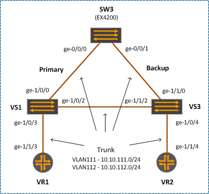
In some scenario, it is more convenient to use RTG to replace STP, e.g. when we do not want to extend the STP domain to “foreign” unmanaged switches, or we want to improve the convergence time. For instance, in the scenario given in the diagram, we will enable RTG on SW3, as we do not want to extend STP domain to VS1 and VS2 (and vice versa).

RTG

Configuration

[edit]
lab@SW03# show interfaces     
ge-0/0/0 {
    description "LINK to VS1";
    unit 0 {
        family ethernet-switching {
            port-mode trunk;
            vlan {
                members 111-112;
            }
        }
    }
}
ge-0/0/1 {
    description "LINK to VS2";
    unit 0 {
        family ethernet-switching {
            port-mode trunk;
            vlan {
                members 111-112;
            }
        }
    }
}

[edit]
lab@SW03# show ethernet-switching-options    
redundant-trunk-group {
    group VS1_and_VS2 {
        preempt-cutover-timer 10;
        interface ge-0/0/0.0 {
            primary;
        }
        interface ge-0/0/1.0;
    }
}

Verification

lab@SW03> show redundant-trunk-group       
Group      Interface   State       Time of last flap                      Flap 
name                                                                      count

VS1_and_VS2 ge-0/0/0.0 Up/Pri/Act  2012-11-28 23:35:08 UTC (00:05:22 ago)     2
           ge-0/0/1.0  Up          Never                                      0

Disable the primary link:

[edit]
lab@MX1# set interfaces ge-1/0/0 disable 

[edit]
lab@MX1# commit 
commit complete

lab@SW03> show redundant-trunk-group    
Group      Interface   State       Time of last flap                      Flap 
name                                                                      count

VS1_and_VS2 ge-0/0/0.0 Dwn/Pri     2012-11-28 23:41:07 UTC (00:00:02 ago)     3
           ge-0/0/1.0  Up/Act      Never                                      0

Recover the primary link:

[edit]
lab@MX1# delete interfaces ge-1/0/0 disable 

[edit]
lab@MX1# commit 

lab@SW03> show redundant-trunk-group    
Group      Interface   State       Time of last flap                      Flap 
name                                                                      count

VS1_and_VS2 ge-0/0/0.0 Up/Pri      2012-11-28 23:41:57 UTC (00:00:07 ago)     4
           ge-0/0/1.0  Up/Act      Never                                      0

Loop will occur if we turn off the redundant trunk group, and RSTP. We may need to trigger the loop by pinging an unknown IP.

lab@SW03# deactivate redundant-trunk-group 

[edit ethernet-switching-options]
lab@SW03# commit 
configuration check succeeds
commit complete

lab@MX1> ping routing-instance VR1 10.10.111.123 
PING 10.10.111.123 (10.10.111.123): 56 data bytes
^C
--- 10.10.111.123 ping statistics ---
2 packets transmitted, 0 packets received, 100% packet loss

lab@SW03> monitor interface ge-0/0/0 

SW03                              Seconds: 57                  Time: 23:44:41
                                                          Delay: 0/0/35
Interface: ge-0/0/0, Enabled, Link is Up
Encapsulation: Ethernet, Speed: 1000mbps
Traffic statistics:                                              Current delta
  Input bytes:               17218698648 (167872912 bps)           [507803328]
  Output bytes:              17278235868 (167871376 bps)           [508118046]
  Input packets:               269042160 (327870 pps)                [7934430]
  Output packets:              269972162 (327870 pps)                [7939338]
Error statistics:
  Input errors:                        0                                   [0]
  Input drops:                         0                                   [0]
  Input framing errors:                0                                   [0]
  Policed discards:                    0                                   [0]
  L3 incompletes:                      0                                   [0]
  L2 channel errors:                   0                                   [0]
  L2 mismatch timeouts:                0                                   [0]
  Carrier transitions:                 5                                   [0]
  Output errors:                       0                                   [0]
  Output drops:                        0                                   [0]
  Aged packets:                        0                                   [0]
Active alarms : None
Active defects: None
Input MAC/Filter statistics:
  Unicast packets                      4  Broadcast packets                [0]

Next='n', Quit='q' or ESC, Freeze='f', Thaw='t', Clear='c', Interface='i'

Note that we can not enable both RSTP and RTG on the same interface. The switch will complain if we try to do so. We can still run RTP on certain interfaces, and RSTP on other interfaces though.

[edit ethernet-switching-options]
lab@SW3# activate redundant-trunk-group 

[edit]
lab@SW3# commit 
error: XSTP : msti 0 STP and RTG cannot be enabled on the same interface ge-0/0/0.0
error: configuration check-out failed

[edit protocols rstp]
lab@SW3# set interface ge-0/0/0 disable 

[edit protocols rstp]
lab@SW3# set interface ge-0/0/1 disable    

[edit protocols rstp]
lab@SW3# top 

[edit]
lab@SW3# commit 
configuration check succeeds

lab@SW3> show spanning-tree interface    

Spanning tree interface parameters for instance 0

Interface    Port ID    Designated      Designated         Port    State  Role
                         port ID        bridge ID          Cost
ge-0/0/0.0     128:513       128:41  32768.aa1111111111     20000  DIS    DIS  
ge-0/0/1.0     128:514       128:51   8192.aa2222222222     20000  DIS    DIS

lab@SW3> show redundant-trunk-group 
Group      Interface   State       Time of last flap                      Flap 
name                                                                      count

VS1_and_VS2 ge-0/0/0.0 Up/Pri/Act  Never                                      0
           ge-0/0/1.0  Up          Never                                      0

Reference

http://www.juniper.net/techpubs/en_US/junos11.4/topics/example/cfm-ex-series-redundant-trunk-groups.html

Multiple Spanning Tree Protocol (MSTP)

In this lab, we are going to configure MSTP such that VS2 is the root bridge for MSTP1 (VLAN111) and MSTP2 (VLAN112); VS1 is the root for MSTP 3 and 4. The forwarding path is as shown in the diagram.

MSTP

Configuration

interfaces {
/* … All VS interfaces are configured in trunk mode, using Enterprise Style */ 
    ge-1/0/1 {
        unit 0 {
            family bridge {
                interface-mode trunk;
                vlan-id-list 111-114;
            }
        }
    }

   … 

}

routing-instances {

    VS1 {                               
        instance-type virtual-switch;
        interface ge-1/0/1.0;
        interface ge-1/0/3.0;
        interface ge-1/0/4.0;
        interface ge-1/1/0.0;
        protocols {
            mstp {
                configuration-name lab4;
                revision-level 1;
                system-identifier aa:11:11:11:11:11;
                interface ge-1/0/1;
                interface ge-1/0/3;
                interface ge-1/0/4;
                msti 1 {
                    vlan 111;
                    interface ge-1/0/1 {
                        cost 100;
                    }
                }
                msti 2 {
                    vlan 112;
                    interface ge-1/0/1 {
                        cost 100;
                    }
                }
                msti 3 {                
                    bridge-priority 8k;
                    vlan 113;
                }
                msti 4 {
                    bridge-priority 8k;
                    vlan 114;
                }
            }
        }
        bridge-domains {
            Customer-bds {
                vlan-id-list 111-114;
            }
        }
    }
    VS2 {
        instance-type virtual-switch;
        interface ge-1/0/2.0;
        interface ge-1/1/1.0;
        protocols {
            mstp {
                configuration-name lab4;
                revision-level 1;
                system-identifier aa:22:22:22:22:22;
                interface ge-1/0/2;
                interface ge-1/1/1;     
                msti 1 {
                    bridge-priority 8k;
                    vlan 111;
                }
                msti 2 {
                    bridge-priority 8k;
                    vlan 112;
                }
                msti 3 {
                    vlan 113;
                }
                msti 4 {
                    vlan 114;
                }
            }
        }
        bridge-domains {
            Customer-bds {
                vlan-id-list 111-114;
            }
        }
    }
    VS3 {
        instance-type virtual-switch;
        interface ge-1/0/5.0;
        interface ge-1/1/2.0;           
        interface ge-1/1/3.0;
        interface ge-1/1/4.0;
        protocols {
            mstp {
                configuration-name lab4;
                revision-level 1;
                system-identifier aa:33:33:33:33:33;
                interface ge-1/1/2;
                interface ge-1/1/3;
                interface ge-1/1/4;
                msti 1 {
                    vlan 111;
                    interface ge-1/1/2 {
                        cost 100;
                    }
                }
                msti 2 {
                    vlan 112;
                    interface ge-1/1/2 {
                        cost 100;
                    }
                }
                msti 3 {
                    vlan 113;
                    interface ge-1/1/3 {
                        cost 100;       
                    }
                }
                msti 4 {
                    vlan 114;
                    interface ge-1/1/4 {
                        cost 100;
                    }
                }
            }
        }
        bridge-domains {
            Customer-bds {
                vlan-id-list 111-114;
            }
        }
    }
}

Verification

Check interface forwarding states

lab@MX1> show l2-learning interface 
Routing Instance Name : VS1
Logical Interface flags (DL -disable learning, AD -packet action drop,
                         LH - MAC limit hit, DN - Interface Down )
Logical             BD         MAC        STP          Logical          
Interface           Name       Limit      State        Interface flags  
ge-1/0/3.0                     8192                   
                    Custom..   1024       Forwarding  
                    Custom..   1024       Forwarding  
                    Custom..   1024       Forwarding  
                    Custom..   1024       Forwarding  
Routing Instance Name : VS1
Logical Interface flags (DL -disable learning, AD -packet action drop,
                         LH - MAC limit hit, DN - Interface Down )
Logical             BD         MAC        STP          Logical          
Interface           Name       Limit      State        Interface flags  
ge-1/0/4.0                     8192                   
                    Custom..   1024       Forwarding  
                    Custom..   1024       Forwarding  
                    Custom..   1024       Forwarding  
                    Custom..   1024       Forwarding  
Routing Instance Name : VS3
Logical Interface flags (DL -disable learning, AD -packet action drop,
                         LH - MAC limit hit, DN - Interface Down )
Logical             BD         MAC        STP          Logical          
Interface           Name       Limit      State        Interface flags  
ge-1/0/5.0                     8192                   
                    Custom..   1024       Forwarding  
                    Custom..   1024       Forwarding  
                    Custom..   1024       Forwarding  
                    Custom..   1024       Forwarding  
Routing Instance Name : VS1
Logical Interface flags (DL -disable learning, AD -packet action drop,
                         LH - MAC limit hit, DN - Interface Down )
Logical             BD         MAC        STP          Logical          
Interface           Name       Limit      State        Interface flags  
ge-1/0/1.0                     8192                   
                    Custom..   1024       Forwarding  
                    Custom..   1024       Forwarding  
                    Custom..   1024       Forwarding  
                    Custom..   1024       Forwarding  
Routing Instance Name : VS2
Logical Interface flags (DL -disable learning, AD -packet action drop,
                         LH - MAC limit hit, DN - Interface Down )
Logical             BD         MAC        STP          Logical          
Interface           Name       Limit      State        Interface flags  
ge-1/1/1.0                     8192                   
                    Custom..   1024       Forwarding  
                    Custom..   1024       Forwarding  
                    Custom..   1024       Forwarding  
                    Custom..   1024       Forwarding  
Routing Instance Name : VS2
Logical Interface flags (DL -disable learning, AD -packet action drop,
                         LH - MAC limit hit, DN - Interface Down )
Logical             BD         MAC        STP          Logical          
Interface           Name       Limit      State        Interface flags  
ge-1/0/2.0                     8192                   
                    Custom..   1024       Forwarding  
                    Custom..   1024       Forwarding  
                    Custom..   1024       Discarding  
                    Custom..   1024       Discarding  
Routing Instance Name : VS1
Logical Interface flags (DL -disable learning, AD -packet action drop,
                         LH - MAC limit hit, DN - Interface Down )
Logical             BD         MAC        STP          Logical          
Interface           Name       Limit      State        Interface flags  
ge-1/1/0.0                     8192                   
                    Custom..   1024       Forwarding  
                    Custom..   1024       Forwarding  
                    Custom..   1024       Forwarding  
                    Custom..   1024       Forwarding  
Routing Instance Name : VS3
Logical Interface flags (DL -disable learning, AD -packet action drop,
                         LH - MAC limit hit, DN - Interface Down )
Logical             BD         MAC        STP          Logical          
Interface           Name       Limit      State        Interface flags  
ge-1/1/3.0                     8192                   
                    Custom..   1024       Discarding  
                    Custom..   1024       Discarding  
                    Custom..   1024       Forwarding  
                    Custom..   1024       Discarding  
Routing Instance Name : VS3
Logical Interface flags (DL -disable learning, AD -packet action drop,
                         LH - MAC limit hit, DN - Interface Down )
Logical             BD         MAC        STP          Logical          
Interface           Name       Limit      State        Interface flags  
ge-1/1/2.0                     8192                   
                    Custom..   1024       Forwarding  
                    Custom..   1024       Forwarding  
                    Custom..   1024       Forwarding  
                    Custom..   1024       Forwarding  
Routing Instance Name : VS3
Logical Interface flags (DL -disable learning, AD -packet action drop,
                         LH - MAC limit hit, DN - Interface Down )
Logical             BD         MAC        STP          Logical          
Interface           Name       Limit      State        Interface flags  
ge-1/1/4.0                     8192                   
                    Custom..   1024       Discarding  
                    Custom..   1024       Discarding  
                    Custom..   1024       Discarding  
                    Custom..   1024       Forwarding

Make sure that all MST instances on all switches agree on the root switch.

lab@MX1> show spanning-tree bridge routing-instance VS1 msti 1 
STP bridge parameters 
Routing instance name               : VS1
Context ID                          : 1
Enabled protocol                    : MSTP

STP bridge parameters for MSTI 1
  MSTI regional root                : 8193.aa:22:22:22:22:22
  Root cost                         : 100
  Root port                         : ge-1/0/1
  Hello time                        : 2 seconds
  Maximum age                       : 20 seconds
  Forward delay                     : 15 seconds
  Hop count                         : 19 
  Number of topology changes        : 3
  Time since last topology change   : 1336 seconds
  Local parameters 
    Bridge ID                       : 32769.aa:11:11:11:11:11

Verify that the spanning tree interface state is as expected

lab@MX1> show spanning-tree interface routing-instance VS1 msti 1 

Spanning tree interface parameters for instance 1

Interface    Port ID    Designated      Designated         Port    State  Role
                         port ID        bridge ID          Cost
ge-1/0/1        128:42       128:52   8193.aa2222222222       100  FWD    ROOT 
ge-1/0/3        128:44       128:44  32769.aa1111111111     20000  FWD    DESG 
ge-1/0/4        128:45       128:45  32769.aa1111111111     20000  FWD    DESG

Rapid Spanning Tree Protocol (RSTP)

In this lab, we are going to configure RSTP with VS2 being the root bridge.

RSTP

Configuration

lab@MX1> show configuration 

interfaces {

/* … All VS interfaces are configured in trunk mode, using Enterprise Style */ 
    ge-1/0/1 {
        unit 0 {
            family bridge {
                interface-mode trunk;
                vlan-id-list 111-114;
            }
        }
    }

    …

}

routing-instances {

    VS1 {                               
        instance-type virtual-switch;
        interface ge-1/0/1.0;
        interface ge-1/0/3.0;
        interface ge-1/0/4.0;
        interface ge-1/1/0.0;
        protocols {
            rstp {
                system-identifier aa:11:11:11:11:11;
                interface ge-1/0/1;
                interface ge-1/0/3;
                interface ge-1/0/4;
            }
        }
        bridge-domains {
            Customer-bds {
                vlan-id-list 111-114;
            }
        }
    }
    VS2 {
        instance-type virtual-switch;
        interface ge-1/0/2.0;
        interface ge-1/1/1.0;
        protocols {
            rstp {
                bridge-priority 8k;     
                system-identifier aa:22:22:22:22:22;
                interface ge-1/0/2;
                interface ge-1/1/1;
            }
        }
        bridge-domains {
            Customer-bds {
                vlan-id-list 111-114;
            }
        }
    }
    VS3 {
        instance-type virtual-switch;
        interface ge-1/0/5.0;
        interface ge-1/1/2.0;
        interface ge-1/1/3.0;
        interface ge-1/1/4.0;
        protocols {
            rstp {
                system-identifier aa:33:33:33:33:33;
                interface ge-1/1/2;
                interface ge-1/1/3;
                interface ge-1/1/4;
            }
        }
        bridge-domains {                
            Customer-bds {
                vlan-id-list 111-114;
            }
        }
    }
}

Verification

Check interface forwarding states

lab@MX1> show l2-learning interface 
Routing Instance Name : VS1
Logical Interface flags (DL -disable learning, AD -packet action drop,
                         LH - MAC limit hit, DN - Interface Down )
Logical             BD         MAC        STP          Logical          
Interface           Name       Limit      State        Interface flags  
ge-1/0/3.0                     8192                   
                    Custom..   1024       Forwarding  
                    Custom..   1024       Forwarding  
                    Custom..   1024       Forwarding  
                    Custom..   1024       Forwarding  
Routing Instance Name : VS1
Logical Interface flags (DL -disable learning, AD -packet action drop,
                         LH - MAC limit hit, DN - Interface Down )
Logical             BD         MAC        STP          Logical          
Interface           Name       Limit      State        Interface flags  
ge-1/0/4.0                     8192                   
                    Custom..   1024       Forwarding  
                    Custom..   1024       Forwarding  
                    Custom..   1024       Forwarding  
                    Custom..   1024       Forwarding  
Routing Instance Name : VS3
Logical Interface flags (DL -disable learning, AD -packet action drop,
                         LH - MAC limit hit, DN - Interface Down )
Logical             BD         MAC        STP          Logical          
Interface           Name       Limit      State        Interface flags  
ge-1/0/5.0                     8192                   
                    Custom..   1024       Forwarding  
                    Custom..   1024       Forwarding  
                    Custom..   1024       Forwarding  
                    Custom..   1024       Forwarding  
Routing Instance Name : VS1
Logical Interface flags (DL -disable learning, AD -packet action drop,
                         LH - MAC limit hit, DN - Interface Down )
Logical             BD         MAC        STP          Logical          
Interface           Name       Limit      State        Interface flags  
ge-1/0/1.0                     8192                   
                    Custom..   1024       Forwarding  
                    Custom..   1024       Forwarding  
                    Custom..   1024       Forwarding  
                    Custom..   1024       Forwarding  
Routing Instance Name : VS2
Logical Interface flags (DL -disable learning, AD -packet action drop,
                         LH - MAC limit hit, DN - Interface Down )
Logical             BD         MAC        STP          Logical          
Interface           Name       Limit      State        Interface flags  
ge-1/1/1.0                     8192                   
                    Custom..   1024       Forwarding  
                    Custom..   1024       Forwarding  
                    Custom..   1024       Forwarding  
                    Custom..   1024       Forwarding  
Routing Instance Name : VS2
Logical Interface flags (DL -disable learning, AD -packet action drop,
                         LH - MAC limit hit, DN - Interface Down )
Logical             BD         MAC        STP          Logical          
Interface           Name       Limit      State        Interface flags  
ge-1/0/2.0                     8192                   
                    Custom..   1024       Forwarding  
                    Custom..   1024       Forwarding  
                    Custom..   1024       Forwarding  
                    Custom..   1024       Forwarding  
Routing Instance Name : VS1
Logical Interface flags (DL -disable learning, AD -packet action drop,
                         LH - MAC limit hit, DN - Interface Down )
Logical             BD         MAC        STP          Logical          
Interface           Name       Limit      State        Interface flags  
ge-1/1/0.0                     8192                   
                    Custom..   1024       Forwarding  
                    Custom..   1024       Forwarding  
                    Custom..   1024       Forwarding  
                    Custom..   1024       Forwarding  
Routing Instance Name : VS3
Logical Interface flags (DL -disable learning, AD -packet action drop,
                         LH - MAC limit hit, DN - Interface Down )
Logical             BD         MAC        STP          Logical          
Interface           Name       Limit      State        Interface flags  
ge-1/1/3.0                     8192                   
                    Custom..   1024       Discarding  
                    Custom..   1024       Discarding  
                    Custom..   1024       Discarding  
                    Custom..   1024       Discarding  
Routing Instance Name : VS3
Logical Interface flags (DL -disable learning, AD -packet action drop,
                         LH - MAC limit hit, DN - Interface Down )
Logical             BD         MAC        STP          Logical          
Interface           Name       Limit      State        Interface flags  
ge-1/1/2.0                     8192                   
                    Custom..   1024       Forwarding  
                    Custom..   1024       Forwarding  
                    Custom..   1024       Forwarding  
                    Custom..   1024       Forwarding  
Routing Instance Name : VS3
Logical Interface flags (DL -disable learning, AD -packet action drop,
                         LH - MAC limit hit, DN - Interface Down )
Logical             BD         MAC        STP          Logical          
Interface           Name       Limit      State        Interface flags  
ge-1/1/4.0                     8192                   
                    Custom..   1024       Discarding  
                    Custom..   1024       Discarding  
                    Custom..   1024       Discarding  
                    Custom..   1024       Discarding

Make sure that all switches agree on the root switch.

lab@MX1> show spanning-tree bridge routing-instance VS1    
STP bridge parameters 
Routing instance name               : VS1
Context ID                          : 1
Enabled protocol                    : RSTP
  Root ID                           : 8192.aa:22:22:22:22:22
  Root cost                         : 20000
  Root port                         : ge-1/0/1
  Hello time                        : 2 seconds
  Maximum age                       : 20 seconds
  Forward delay                     : 15 seconds
  Message age                       : 1 
  Number of topology changes        : 2
  Time since last topology change   : 55 seconds
  Local parameters 
    Bridge ID                       : 32768.aa:11:11:11:11:11
    Extended system ID              : 0

Verify that the spanning tree interface state is as expected

lab@MX1> show spanning-tree interface routing-instance VS1                

Spanning tree interface parameters for instance 0

Interface    Port ID    Designated      Designated         Port    State  Role
                         port ID        bridge ID          Cost
ge-1/0/1        128:42       128:52   8192.aa2222222222     20000  FWD    ROOT 
ge-1/0/3        128:44       128:44  32768.aa1111111111     20000  FWD    DESG 
ge-1/0/4        128:45       128:45  32768.aa1111111111     20000  FWD    DESG

Q-in-Q

Task

In this lab, we will configure and verify Q-in-Q operation.

QinQ Routed

Step 1: MX5 configured with Access ports, and SW1 & SW2 port are standard access to verify physical connectivity.

MX5

interfaces {
    ge-1/0/2 {
        unit 0 {
            family inet {
                address 10.1.1.1/24;
            }
        }
    }
    ge-1/1/2 {
        unit 0 {
            family inet {
                address 10.1.1.2/24;
            }
        }
    }
}

protocols {
    lldp {
        interface all;
    }
}
routing-instances {
    R2 {
        instance-type virtual-router;
        interface ge-1/1/2.0;
        routing-options {
            router-id 10.1.1.2;
        }
    }
}

SW1

interfaces {
    ge-0/0/0 {
        unit 0 {
            family ethernet-switching {
                port-mode trunk;        
                vlan {
                    members all;
                }
            }
        }
    }

    ge-0/0/2 {
        unit 0 {
            family ethernet-switching;
        }
    }
}

vlans {
    QinQ_Vlan {
        description "Test Q-in-Q VLAN";
        vlan-id 111;
        interface {
            ge-0/0/2.0;
        }
    }
}

SW2

interfaces {
    ge-1/0/0 {
        unit 0 {
            family ethernet-switching {
                port-mode trunk;
                vlan {
                    members all;
                }
            }
        }
    }
    ge-1/0/2 {
        description "TEST to MX5";
        unit 0 {
            family ethernet-switching;
        }
    }
}

vlans {
    QinQ_Vlan {
        description "Test Q-in-Q VLAN";
        vlan-id 111;
        interface {
            ge-1/0/2.0;
        }
    }
}

Verification:

admin@MX5> ping 10.1.1.2    
PING 10.1.1.2 (10.1.1.2): 56 data bytes
64 bytes from 10.1.1.2: icmp_seq=0 ttl=64 time=0.582 ms
64 bytes from 10.1.1.2: icmp_seq=1 ttl=64 time=0.530 ms
^C

Step 2: Convert the MX5 interfaces to the Dot1Q

R1 R2 connectivity will break, as the current switch configuration does not support Dot1Q config.

MX5

interfaces {
    ge-1/0/2 {
        vlan-tagging;
        unit 0 {
            vlan-id 100;
            family inet {
                address 10.1.1.1/24;
            }
        }
    }
    ge-1/1/2 {
        vlan-tagging;
        unit 0 {
            vlan-id 100;
            family inet {
                address 10.1.1.2/24;
            }
        }
    }
}

The pings fail as expected, because EX switches do not expected VLAN tagging on Access Ports.

admin@MX5> ping 10.1.1.2 count 5 rapid       
PING 10.1.1.2 (10.1.1.2): 56 data bytes
.....
--- 10.1.1.2 ping statistics ---
5 packets transmitted, 0 packets received, 100% packet loss

Step 3: Convert the EX interfaces into a Q-in-Q

{master:0}[edit vlans QinQ_Vlan]
admin@SW1# set dot1q-tunneling customer-vlans 1-4094 

{master:0}[edit vlans QinQ_Vlan]
admin@SW1# show 
description "Test Q-in-Q VLAN";
vlan-id 111;
interface {
    ge-0/0/2.0;
}
dot1q-tunneling {
    customer-vlans 1-4094;
}

{master:0}[edit vlans QinQ_Vlan]
admin@SW1# commit 
error: Trunk interface <ge-0/0/0.0> can not be memeber of both dot1q-tunneling enabled vlan <QinQ_Vlan>, and a non dot1q-tunneled vlan <TEST_VLAN> when dot1q-tunneling ethernet-type is not 
error: configuration check-out failed

admin@SW1# top        

{master:0}[edit]
admin@SW1# edit ethernet-switching-options 

{master:0}[edit ethernet-switching-options]
admin@SW1# set dot1q-tunneling ether-type 0x
                                                      ^
'0x' is ambiguous.
Possible completions:
  0x8100               Dot1q ether-type value 0x8100
  0x88a8               Dot1q ether-type value 0x88a8
  0x9100               Dot1q ether-type value 0x9100
{master:0}[edit ethernet-switching-options]
admin@SW1# set dot1q-tunneling ether-type 0x8100 

{master:0}[edit ethernet-switching-options]
admin@SW1# commit

Below is full Q-in-Q switch config:

SW1

ethernet-switching-options {
    dot1q-tunneling {
        ether-type 0x8100;
    } 
}
vlans {
    QinQ_Vlan {
        description "Test Q-in-Q VLAN";
        vlan-id 111;
        interface {
            ge-0/0/2.0;
        }
        dot1q-tunneling {
            customer-vlans 1-4094;
        }
    }
}

interfaces {
    ge-0/0/0 {
        unit 0 {
            family ethernet-switching {
                port-mode trunk;        
                vlan {
                    members all;
                }
            }
        }
    }

    ge-0/0/2 {
        unit 0 {
            family ethernet-switching;
        }
    }
}

SW2


ethernet-switching-options {
    dot1q-tunneling {
        ether-type 0x8100;              
    }
}

vlans {
    QinQ_Vlan {
        description "Test Q-in-Q VLAN";
        vlan-id 111;
        interface {
            ge-1/0/2.0;
        }
        dot1q-tunneling {
            customer-vlans 1-4094;
        }
    }
}

interfaces {
    ge-1/0/0 {
        unit 0 {
            family ethernet-switching {
                port-mode trunk;        
                vlan {
                    members all;
                }
            }
        }
    }

    ge-1/0/2 {
        unit 0 {
            family ethernet-switching;
        }
    }
}

Verification:

admin@MX5> ping 10.1.1.2 count 5 rapid    
PING 10.1.1.2 (10.1.1.2): 56 data bytes
!!!!!
--- 10.1.1.2 ping statistics ---
5 packets transmitted, 5 packets received, 0% packet loss
round-trip min/avg/max/stddev = 0.418/0.689/1.621/0.469 ms

admin@SW1> show configuration vlans 
QinQ_Vlan {
    description "Test Q-in-Q VLAN";
    vlan-id 111;
    interface {
        ge-0/0/2.0;
    }
    dot1q-tunneling {
        customer-vlans 1-4094;
    }
}

admin@SW1> show vlans QinQ_Vlan extensive 
VLAN: QinQ_Vlan, Created at: Tue Sep 11 09:20:46 2012
802.1Q Tag: 111, Internal index: 5, Admin State: Enabled, Origin: Static
Description: Test Q-in-Q VLAN
Dot1q Tunneling status: Enabled
Customer VLAN ranges:
      1-4094
Protocol: Port Mode, Mac aging time: 300 seconds
Number of interfaces: Tagged 1 (Active = 1), Untagged  1 (Active = 1)
      ge-0/0/0.0*, tagged, trunk
      ge-0/0/2.0*, untagged, access

Step 5: Change MX5 interfaces to use no tagging interface

This is to test if current Q-in-Q support customer’s native VLAN without a tag.

admin@MX5> ping 10.1.1.2 
PING 10.1.1.2 (10.1.1.2): 56 data bytes
^C
--- 10.1.1.2 ping statistics ---
5 packets transmitted, 0 packets received, 100% packet loss

This confirms that the above Q-in-Q config does not support the native VLAN traffic.

Step 6: Change the Q-in-Q config to support customer native VLAN as well

To support customer untagged traffic, change the VLAN dot1q-tunneling configuration options:

admin@SW1> show configuration vlans QinQ_Vlan    
description "Test Q-in-Q VLAN";
vlan-id 111;
interface {
    ge-0/0/2.0;
}
dot1q-tunneling {
    customer-vlans [ native 1-4094 ];
    layer2-protocol-tunneling {
        all;
    }
}

admin@SW2> show configuration vlans QinQ_Vlan 
description "Test Q-in-Q VLAN";
vlan-id 111;
interface {
    ge-1/0/2.0;
}
dot1q-tunneling {
    customer-vlans [ native 1-4094 ];
    layer2-protocol-tunneling {
        all;
    }
}

admin@MX5> ping 10.1.1.2 count 2 
PING 10.1.1.2 (10.1.1.2): 56 data bytes
64 bytes from 10.1.1.2: icmp_seq=0 ttl=64 time=0.604 ms
64 bytes from 10.1.1.2: icmp_seq=1 ttl=64 time=0.530 ms

--- 10.1.1.2 ping statistics ---
2 packets transmitted, 2 packets received, 0% packet loss
round-trip min/avg/max/stddev = 0.530/0.567/0.604/0.037 ms

Step 7: Create virtual switches to verify that the Q-in-Q successfully carry the L2 control traffic (such as STP)

QinQ Switch

admin@MX5> show configuration interfaces 
ge-1/0/2 {
    unit 0 {
        family bridge {
            interface-mode trunk;
            vlan-id-list 100;
        }
    }
}
ge-1/1/2 {
    unit 0 {
        family bridge {
            interface-mode trunk;
            vlan-id-list 100;
        }
    }
}

admin@MX5> show configuration routing-instances 
CSW1 {
    description "Virtual SW1";
    instance-type virtual-switch;
    interface ge-1/0/2.0;
    protocols {
        rstp {
            bridge-priority 4k;
            system-identifier a8:11:11:11:11:11;
            interface ge-1/0/2;
        }
    }
}
CSW2 {
    description "Virtual SW2";
    instance-type virtual-switch;
    interface ge-1/1/2.0;
    protocols {
        rstp {
            bridge-priority 8k;
            system-identifier a8:22:22:22:22:22;
            interface ge-1/1/2;
        }
    }
}

admin@MX5> show lldp neighbors    
Local Interface Chassis Id        Port info     System Name
ge-1/1/2        a8:d0:e5:55:26:b0  ge-1/0/2     MX5          
ge-1/0/2        a8:d0:e5:55:26:b0  ge-1/1/2     MX5

This confirms that LLDP traffic is carried across Q-in-Q

Below show output confirm that RSTP is working across the Q-in-Q circuit. Note that switches agree on the same STP root, and the switch port roles are expected (designated, root).

admin@MX5> show spanning-tree bridge routing-instance CSW2  
STP bridge parameters 
Routing instance name               : CSW2
Context ID                          : 2
Enabled protocol                    : RSTP
  Root ID                           : 4096.a8:11:11:11:11:11
  Root cost                         : 20000
  Root port                         : ge-1/1/2
  Hello time                        : 2 seconds
  Maximum age                       : 20 seconds
  Forward delay                     : 15 seconds
  Message age                       : 1 
  Number of topology changes        : 2
  Time since last topology change   : 1878 seconds
  Local parameters 
    Bridge ID                       : 8192.a8:22:22:22:22:22
    Extended system ID              : 0

admin@MX5> show spanning-tree bridge routing-instance CSW1       
STP bridge parameters 
Routing instance name               : CSW1
Context ID                          : 1
Enabled protocol                    : RSTP
  Root ID                           : 4096.a8:11:11:11:11:11
  Hello time                        : 2 seconds
  Maximum age                       : 20 seconds
  Forward delay                     : 15 seconds
  Message age                       : 0 
  Number of topology changes        : 3
  Time since last topology change   : 1938 seconds
  Local parameters 
    Bridge ID                       : 4096.a8:11:11:11:11:11
    Extended system ID              : 0

admin@MX5> show spanning-tree interface routing-instance CSW2  

Spanning tree interface parameters for instance 0

Interface    Port ID    Designated      Designated         Port    State  Role
                         port ID        bridge ID          Cost
ge-1/1/2        128:53       128:43   4096.a81111111111     20000  FWD    ROOT 

admin@MX5> show spanning-tree interface routing-instance CSW1    

Spanning tree interface parameters for instance 0

Interface    Port ID    Designated      Designated         Port    State  Role
                         port ID        bridge ID          Cost
ge-1/0/2        128:43       128:43   4096.a81111111111     20000  FWD    DESG

Note:

Note that the “monitor traffic interface” command can not be used to monitor traffic that is switched by EX interfaces, as it is not traffic handled by Routing Engine.

http://www.juniper.net/techpubs/en_US/junos10.0/information-products/topic-collections/swcmdref-basics-services/monitor-traffic.html

Reference:

http://kb.juniper.net/InfoCenter/index?page=content&id=KB12259
http://www.juniper.net/techpubs/en_US/junos10.2/topics/concept/qinq-tunneling-ex-series.html

Difference between traffic-engineering options: bgp-igp vs mpls-forwarding

In the previous post on tunnelling ldp over rsvp we  have briefly discussed the option traffic-engineering bgp-igp, which we need to turn on on PE1 so we can use the LSP path with the trace-route to PE2 loopback for verification/demonstration purpose.

Today, we go into more details on the two options, that are quite similar in that regard.

traffic-engineering bgp-igp

install LSP as the best route in inet.0 table, as well as in forwarding table.

traffic-engineering mpls-forwarding

install LSP in inet.0 table for forwarding only. It can be used for next hop look up. But it is installed in the inet.0 table with a higher admin distance, i.e. less preferred than IGP route.

As far as tracing from PE1 to PE2 loopback is concerned, the two commands do the same job: LSP is used for forwarding traffic.

lab@PE1# show protocols mpls 
traffic-engineering bgp-igp;

lab@PE1# run show route 192.168.1.2 

inet.0: 29 destinations, 33 routes (29 active, 0 holddown, 0 hidden)
+ = Active Route, - = Last Active, * = Both

192.168.1.2/32     *[LDP/9] 00:02:28, metric 1
                    > to 172.22.210.2 via em1.210, Push 300240
                    [OSPF/10] 00:02:30, metric 4
                    > to 172.22.210.2 via em1.210

lab@PE1# run traceroute 192.168.1.2 
traceroute to 192.168.1.2 (192.168.1.2), 30 hops max, 40 byte packets
 1  172.22.210.2 (172.22.210.2)  0.461 ms  0.388 ms  0.243 ms
     MPLS Label=300240 CoS=0 TTL=1 S=1
 2  172.22.201.2 (172.22.201.2)  0.498 ms  0.459 ms  0.355 ms
     MPLS Label=300528 CoS=0 TTL=1 S=0
     MPLS Label=300240 CoS=0 TTL=1 S=1
 3  172.22.206.2 (172.22.206.2)  0.634 ms  0.570 ms  0.602 ms
     MPLS Label=300240 CoS=0 TTL=1 S=1
 4  192.168.1.2 (192.168.1.2)  0.876 ms  0.991 ms  0.861 ms

[edit]
lab@PE1# set protocols mpls traffic-engineering mpls-forwarding 
[edit]
lab@PE1# commit 
commit complete

[edit]
lab@PE1# show protocols mpls 
traffic-engineering mpls-forwarding;

lab@PE1# run show route 192.168.1.2                                

inet.0: 29 destinations, 33 routes (29 active, 0 holddown, 0 hidden)
@ = Routing Use Only, # = Forwarding Use Only
+ = Active Route, - = Last Active, * = Both

192.168.1.2/32     @[OSPF/10] 00:04:19, metric 4
                    > to 172.22.210.2 via em1.210
                   #[LDP/9] 00:00:28, metric 1
                    > to 172.22.210.2 via em1.210, Push 300240

inet.3: 3 destinations, 3 routes (3 active, 0 holddown, 0 hidden)
+ = Active Route, - = Last Active, * = Both

192.168.1.2/32     *[LDP/9] 00:00:28, metric 1
                    > to 172.22.210.2 via em1.210, Push 300240

lab@PE1# run traceroute 192.168.1.2                                
traceroute to 192.168.1.2 (192.168.1.2), 30 hops max, 40 byte packets
 1  172.22.210.2 (172.22.210.2)  0.905 ms  0.312 ms  0.272 ms
     MPLS Label=300240 CoS=0 TTL=1 S=1
 2  172.22.201.2 (172.22.201.2)  0.417 ms  0.401 ms  0.414 ms
     MPLS Label=300528 CoS=0 TTL=1 S=0
     MPLS Label=300240 CoS=0 TTL=1 S=1
 3  172.22.206.2 (172.22.206.2)  0.572 ms  0.683 ms  0.899 ms
     MPLS Label=300240 CoS=0 TTL=1 S=1
 4  192.168.1.2 (192.168.1.2)  0.943 ms  1.180 ms  0.824 ms

As we can see, tracing looks the same! No difference in the packet forwarding decision.

However, the difference is in the routing selection process, i.e. in the control plane. When we use traffic-engineering bgp-igp option, it may change the protocol associated with the best route, and may change the routing outcome (e.g. with routing-policy that match based on the source protocol). On the other hand, traffic-engineering mpls-forwarding does not change the routing behaviour.

To demonstrate this behaviour, we create a policy to export OSPF route into eBGP to CE1.

[edit protocols bgp]
lab@PE1# show 
# delete advertise-inactive 
group my-ext-group {
    type external;
    export OSPF-to-BGP;
    peer-as 65101;
    neighbor 10.0.10.2;
}

lab@PE1# top show policy-options     
policy-statement OSPF-to-BGP {
    term 1 {
        from {
            protocol ospf;
            route-filter 192.168.1.2/32 exact;
        }
        then accept;
    }
}

In the below example, as we use mpls-forwarding option, the route 192.168.1.2/32 gets advertised from OSPF into BGP.

[edit protocols mpls]
lab@PE1# show 
traffic-engineering mpls-forwarding;

[edit protocols mpls]

lab@PE1# run show route advertising-protocol bgp 10.0.10.2    

inet.0: 29 destinations, 33 routes (29 active, 0 holddown, 0 hidden)
  Prefix                  Nexthop              MED     Lclpref    AS path
* 10.0.11.0/24            Self                                    65102 I
@ 192.168.1.2/32          Self                 4                  I
* 192.168.11.2/32         Self                                    65102 I

But with the below config, the same route does not get advertised from OSPF to BGP

lab@PE1# show                               
traffic-engineering bgp-igp;

lab@PE1# run show route 192.168.1.2    

inet.0: 29 destinations, 33 routes (29 active, 0 holddown, 0 hidden)
+ = Active Route, - = Last Active, * = Both

192.168.1.2/32     *[LDP/9] 00:01:02, metric 1
                    > to 172.22.210.2 via em1.210, Push 300240
                    [OSPF/10] 00:27:55, metric 4
                    > to 172.22.210.2 via em1.210

[edit protocols mpls]
lab@PE1# run show route advertising-protocol bgp 10.0.10.2    

inet.0: 29 destinations, 33 routes (29 active, 0 holddown, 0 hidden)
  Prefix                  Nexthop              MED     Lclpref    AS path
* 10.0.11.0/24            Self                                    65102 I
* 192.168.11.2/32         Self                                    65102 I

The route 192.168.1.2/32 is not advertised to CE1, because it is no longer OSPF active route.

Reference

http://www.juniper.net/techpubs/en_US/junos9.5/information-products/topic-collections/config-guide-mpls-applications/mpls-configuring-traffic-engineering-for-lsps.html

When you configure an LSP, a host route (a 32-bit mask) is installed in the ingress router toward the egress router; the address of the host route is the destination address of the LSP. Typically, you configure the BGP option (traffic-engineering bgp), allowing only BGP to use LSPs in its route calculations . The other traffic-engineering statement options, allow you to alter this behavior in the master instance. This functionality is not available for specific routing instances. Also, you can enable only one of the traffic-engineering statement options (bgp, bgp-igp, bgp-igp-both-ribs, or mpls-forwarding) at a time.

Using RSVP and LDP Routes for Traffic Forwarding

Configure the bgp-igp option of the traffic-engineering statement to cause BGP and the interior gateway protocols (IGPs) to use LSPs for forwarding traffic destined for egress routers. The bgp-igp option causes all inet.3 routes to be moved to the inet.0 routing table.

On the ingress router, include the traffic-engineering bgp-igp statement:

traffic-engineering bgp-igp;

Using RSVP and LDP Routes for Forwarding But Not Route Selection

If you configure the traffic-engineering bgp-igp statement or the traffic-engineering bgp-igp-both-ribs statement, high-priority RSVP and LDP routes can supersede IGP routes in the inet.0 routing table. IGP routes might no longer be redistributed since they are no longer the active routes.

When you configure the mpls-forwarding option at either the [edit logical-systems logical-system-name protocols mpls traffic-engineering] hierarchy level or the [edit protocols mpls traffic-engineering] hierarchy level, RSVP and LDP routes are used for forwarding but are excluded from route selection. These routes are added to both the inet.0 and inet.3 routing tables. RSVP and LDP routes in the inet.0 routing table are given a low preference when the active route is selected. However, RSVP and LDP routes in the inet.3 routing table are given a normal preference and are therefore used for selecting forwarding next hops.

When you activate the mpls-forwarding option, routes whose state is ForwardingOnly are preferred for forwarding even if their preference is lower than that of the currently active route. To examine the state of a route, execute a show route detail command.

To configure, include the traffic-engineering mpls-forwarding statement:

traffic-engineering mpls-forwarding;